A fourth-axis CNC router and an ordinary wood lathe are not interchangeable simply because both rotate wood. For a continuous, rotationally symmetrical outer contour, ordinary turning may be the direct approach. When the design also needs programmed detail around the circumference or at defined angular positions, rotary CNC carving becomes a different process to consider. The feature you want to make—not the round blank—sets the comparison.
This comparison concerns an ordinary wood lathe used with supported hand-held cutting tools, not every specialized or CNC-controlled turning machine. It also assumes that the proposed CNC setup can actually hold the blank and reach the required feature. Neither a familiar-looking chuck nor a digital model establishes those conditions by itself.
The Same Outline Can Hide Two Different Jobs
Consider a hypothetical small decorative wooden component with a rounded outside profile. In its first version, the outer contour is the whole design: viewed around the rotation axis, the same profile continues all the way around. There is no inscription that must face a particular direction and no local recess that interrupts the contour. The job is to form that rotational shape.
Ordinary woodturning addresses this kind of task by rotating the wood while the turner guides a cutting tool supported on a toolrest. The American Association of Woodturners describes the basic process in terms of shaping forms symmetrical around an axis. The maker controls the developing contour through tool presentation and observation; a programmed angular pattern is not part of this version of the design.
Now keep the same outside profile but add a decorative motif at selected positions around its middle. Suppose one motif must face the same direction as a separate reference feature elsewhere on the component. This is a hypothetical design requirement, not an ED1 machining trial. The component still looks broadly round, but its detail now has both a shape and an orientation. Making a good rounded contour would leave that second job unfinished.
Rotary CNC routing can be relevant to the second job because the cutting path and the stock’s angular presentation can be planned together. A pattern that follows the cylindrical surface differs from a feature reached at one selected orientation. Autodesk’s wrap-toolpath reference describes mapping a path around a specified cylindrical radius; it also explains that tool direction affects the geometry of features cut into a cylinder. A visually similar recess does not necessarily call for the same machining approach.
That does not mean every local decoration requires a fourth axis. A single inscription reachable from one fixed orientation may need no rotary operation at all. Nor does it mean ordinary turning can never produce non-round or decorated work: specialized multiaxis and ornamental turning exist. The useful distinction is the process required by this design, not an absolute division between plain and decorative objects.
Preparing a Shape Is Different From Preparing a Toolpath
In ordinary turning, the maker guides the cutting tool as the form develops. Tool control and the ability to judge the changing contour are central skills. A simple-looking rounded shape is not automatically an easy or safe turning exercise, and describing the process as hand-guided is not a claim that its results are inherently less accurate.
Rotary CNC routing moves much of the preparation ahead of the cut. The geometry, cutter, holding arrangement and toolpath must form a workable combination before the program runs. The digital design needs to express the actual feature, including the relationship between its position and the part’s reference. A decorative image placed on a model is not yet a machining plan.
For the hypothetical component, this changes what preparation is useful. If the only requirement is the continuous rounded profile, creating a rotary carving model does not establish an additional benefit. If the design needs the positioned motif, the digital work has a defined purpose: describing that detail and where it belongs. It is then worth evaluating a machine and path strategy capable of making it, rather than adding CNC preparation simply because the stock is cylindrical.
Specific CAM methods also have boundaries. The cylindrical wrap feature described by Autodesk requires a cylinder, not a cone or irregular surface. That limitation belongs to the documented method; it is not a rule that all rotary machining must use the same geometry. Likewise, the documentation does not establish which software edition, post-processor or machine configuration supports a particular project. Those are separate requirements from understanding what the feature needs.
A CNC wood lathe is another category to evaluate on its own merits. Automation of a turning process does not make it equivalent to a rotary-equipped router, and the capabilities of a specialist machine cannot be transferred to a desktop accessory by name alone. Comparing actual processes is more useful than treating “CNC” as a single capability shared by every machine.
A Turned Blank Must Still Be a Machinable CNC Blank
A turn-then-carve route can be reasonable when the rounded form and the programmed detail genuinely benefit from different processes. But the part leaving the first machine must still be suitable for the next operation. The transfer introduces a new holding and reference problem; it does not disappear because the blank is already round.
Return to the hypothetical decorative component. Turning its outside profile may complete the rotational shape, but the later carving operation still needs material that can be gripped or supported without obstructing the motif. If the first process removes every suitable contact region, the attractive finished contour may leave no workable way to carry out the second operation. Reserving a region for holding is only useful if the later setup can actually use it.
Orientation is a separate issue. If the motif can face any direction on an otherwise featureless cylinder, there may be no pre-existing angular relationship to preserve. If it must line up with a reference feature, the next setup must establish that relationship. The round outline alone does not identify which direction should become the front. Moving the part between chucks does not, by itself, preserve an angular reference or establish alignment.
The reference feature need not have been made by turning, and it should not be assumed that ordinary turning creates a flat facet. What matters is whether the required reference remains available and meaningful when the part is held for carving. If a prior operation removes it, or if the new hold conceals it, the design or sequence needs reconsideration before the decorative detail is committed.
Tool access can also change during transfer. A feature may be clear in the model but lie too close to the chosen grip or support once the real blank is installed. Its position relative to the chuck, support, cutter and holder matters throughout the planned motion. Combining processes is therefore a conditional choice: it is useful only when the partly finished component remains supportable, locatable and accessible for the work that remains.
Where the ED1 Fourth-Axis Kit Enters the Decision
Once a project has a real need for rotary CNC access, the ED1 fourth-axis CNC rotary module kit is the dedicated accessory to evaluate for the ED1 desktop CNC router. TwoTrees presents the matching platform’s rotary applications in terms of cylinders, curved objects and multi-sided carving. That is a CNC carving role, not a reason to treat the accessory as a wood lathe or add hand-held turning tools or a toolrest to the router.
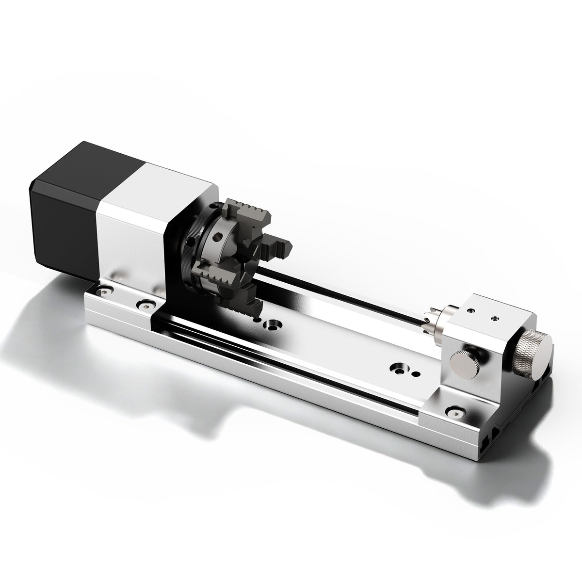
The ED1 page lists maximum A-axis clamping bounds of 100 mm in length and 50 mm in diameter. These are manufacturer-stated clamping limits, not a guarantee that a design of those dimensions can be fully machined. Stock, gripping and support allowances, tool reach, the holder and the required cutter path all contribute to the actual project fit.

For the decorative component, the accessory becomes relevant when the planned detail actually benefits from presenting the part around its circumference. It does not resolve an inaccessible feature, provide a missing transfer reference or make every surface available to the cutter. Evaluate the dedicated hardware against those remaining requirements, rather than letting the availability of a rotary kit determine the design.
The plain-profile version and the positioned-motif version can therefore lead to different choices despite starting from similar blanks. The first can be completed when its rotational contour meets the design requirement. The second still needs the local detail and its intended orientation. If that second job cannot be held and referenced after turning, change the sequence, preserve a suitable region where the design permits, or reconsider the process before finishing away the material needed to complete it. A successful process choice accounts for the feature that remains to be made, not just the shape already achieved.