A center-cutting end mill has at least one end cutting edge that reaches its rotational axis. A non-center-cutting end mill leaves a central noncutting region. The distinction matters when starting a cut in solid stock: the cutter needs an edge where the material must be removed, not just cutting edges around its outside.
Center-cutting geometry makes that central cutting action possible, but it is not a universal instruction to plunge. The useful decision combines the end-face design with the material present at the start of the move and the exact tool’s permitted applications. Two end mills that look similar from the side can demand different entry plans.
Look beyond the spiral flutes
The spiral grooves visible along an end mill describe its flutes, not everything happening on its end face. Flute count, cutting diameter and a flat-ended shape each describe a different feature. None alone establishes that a cutting edge reaches the axis. Sundi’s explanation of center-cutting and non-center-cutting end mills makes this end-face distinction explicit.
That is why a description such as “two-flute spiral end mill” is useful but incomplete for deciding how an operation begins. It identifies a cutter family; it does not make every member of that family interchangeable. When browsing TwoTrees CNC router bits and end mills, distinguish the geometry needed to create the finished feature from the geometry needed to enter the material in the first place.

A full straight plunge into unbroken stock brings the end face toward material beneath the tool’s center as well as its circumference. A central region without cutting geometry cannot be made into a cutting edge by selecting a different feed field in CAM. Conversely, an edge reaching the center does not establish an appropriate plunge rate or prove that chips can escape from the proposed feature.
The center turns, but it does not travel around a circle
Spindle RPM can make this distinction seem counterintuitive. The whole tool rotates together, so why should the center behave differently from the outside? Every point completes the same number of revolutions, but it does not travel the same distance. A point near the circumference follows a large circle; a point close to the axis follows a much smaller one.
Sandvik Coromant distinguishes spindle speed, measured in revolutions per minute, from cutting speed, the surface speed at the cutting edge. Its milling formulas also account for the effective cutting diameter. The underlying circular-motion relationship can be written as v = 2πrn, where r is distance from the axis, n is revolutions per minute and v is tangential distance traveled per minute in consistent length units.
At the same RPM, a point halfway from the axis to the outside radius has half the outside point’s tangential speed. At the exact axis, the rotational tangential component is zero. This is a geometric comparison, not a cutting-parameter recommendation. It explains why an RPM value for the spindle does not describe identical cutting conditions across the entire end face.
Zero rotational tangential speed does not mean zero movement toward the stock. During an axial feed, the cutter still advances along its axis. Rotation and translation are different motions, and the end geometry must accommodate the material encountered during that advance. Increasing RPM cannot supply a cutting edge where a non-center-cutting tool has none.
Keep the recess, change where the cut starts
Consider a hypothetical small wooden panel with a flat-bottomed recess enclosed on every side. Before any machining, solid wood occupies the starting location. If the proposed first move descends straight into that location, material is present beneath the entire tool end, including its central region. The planned pocket floor may be flat, but a flat-ended cutter alone does not answer the entry question.
A center-cutting end mill addresses that particular geometric requirement. The remaining application decision concerns the exact tool, material, engagement and chip-clearance conditions. KYOCERA SGS’s discussion of plunge and ramp milling emphasizes that the strategy must suit the tool geometry and the machining conditions. A center-cutting label is one part of that decision, not a substitute for it.
Now change the hypothetical recess so it opens at the edge of the panel. The desired floor and wall finish may be similar, yet the tool can potentially begin outside the stock and enter laterally at the intended cutting level. It no longer necessarily needs to create its starting opening by descending through a full disk of solid material.
That makes the non-center-cutting distinction relevant in a different way. The question becomes whether the planned approach and remaining stock keep the noncutting region clear while the working edges engage appropriately. A non-center-cutting tool can have a legitimate lateral milling role; it is not simply an inferior version of a center-cutting tool. The starting geometry has changed the demand placed on the end face.
An already cleared cavity changes the same material-location question. Its existence on the drawing is not enough: the actual empty region must accommodate the cutter and the proposed movement. A small opening that leaves stock under part of the noncutting region does not make that remaining stock disappear. Think about the material the tool will actually encounter rather than treating any hole as equivalent to a cleared entry space.
These examples are conceptual comparisons, not instructions to run a particular toolpath. They show why two otherwise similar recesses can call for different starting strategies, and why a tool selected for the final walls and floor must also be suitable for reaching them.
Plan the entry as part of the ED1 operation
Ramping combines lateral and axial movement; a helical entry follows a circular descent. Those paths change engagement, but neither is an automatic workaround for every non-center-cutting tool. The cutter’s rated entry modes and the space available in the feature still govern the choice. A helix that fits on screen does not, by itself, establish an appropriate physical engagement.
For a panel planned on the ED1 enclosed desktop CNC router, carry the entry decision through each operation. A clearing tool and a detail tool may approach different regions of the same part. The clearing tool’s accepted start does not automatically qualify a later tool descending into a smaller feature, even when both tools belong to the same general cutter family.
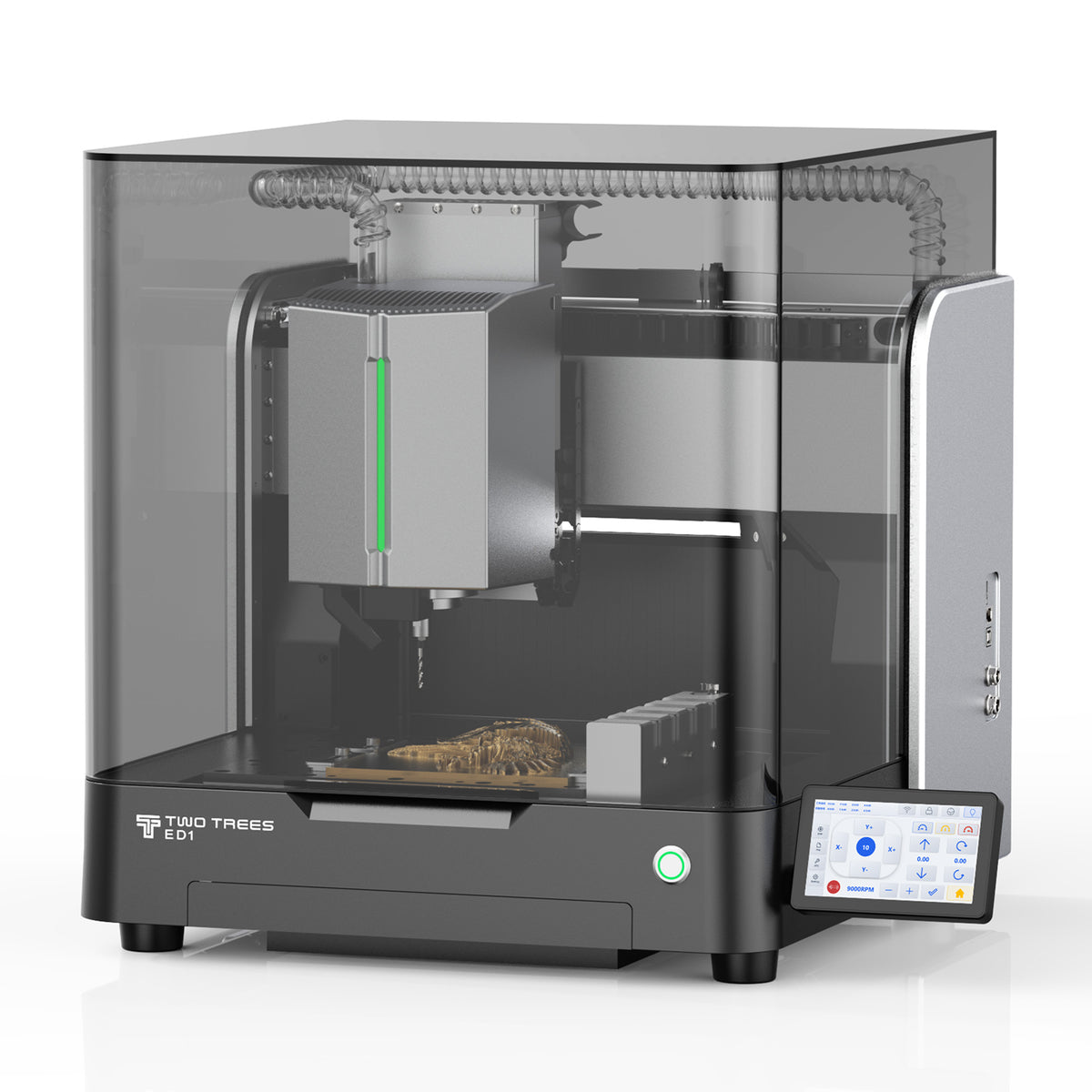
Automatic tool changing handles a tool exchange. It does not change a cutter’s end geometry or make its entry capability identical to the tool used before it. Likewise, matching a shank to a supported holder answers a fit question, not the separate question of whether the end face supports a chosen move. Keep those decisions connected without treating any one of them as proof of the others.
Before hands-on inspection or tool work, stop the spindle and safely isolate the equipment according to its manufacturer’s procedure. Use the specified workholding, extraction and protective measures, and supervise machining. Do not try to overcome an unsuitable entry by bypassing a guard or forcing the tool through an unstable move.
The useful classification is therefore tied to the material present at entry. When the axis must address unbroken stock, select a tool and supported starting strategy that can do that work. When access from outside the stock or an existing cleared region changes the engagement, assess that actual geometry. Flute count, higher RPM and a different CAM path name cannot supply cutting action that the tool does not possess.
A related terminology question
Does “center-cutting” mean the tool is self-centering? No. Center cutting describes cutting geometry at the rotational axis. It does not describe a mechanism that locates the workpiece, finds a feature’s center or corrects the position of the programmed toolpath.